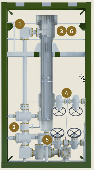
Refer to the numbered graphic below for the steps involved with batch discharge of solids from the wellhead-screen filter.
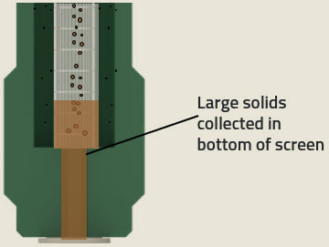
- The operating wellhead screen-filter is filled with solids. This was covered in the previous post on particle travel. The separated solids are collected at the bottom of the screen element.
- Once the wellhead screen-filter is full of solids (typically indicated by high pressure drop), then the entire operating filter unit is taken offline for batch discharge. The standby unit is put into operation to maintain separation duty of the system.
- The retained (high) operating pressure and gases are vented from the unit to be discharged of solids.
- The solids are purged from the wellhead screen-filter using utility water. This should be from a clean or suitable source. Recommended pressure is 3-6 barg (50-100 psig) at 12.5-23.8 m³/hr (55-105 gpm) flow rate.
- The slurry discharged from bottom of screen through the purge valve. At the recommended flush water flow rate, and allowing for a 3X purge volume, the purge time should range from 30-45 seconds. However, you may need to add additional time to transport the purged solids through the piping to the disposal site.
- Once the solids are removed, the purge valve is closed, then the unit is re-pressurized and ready to go back on-line.