
Facilities Sand Management: Particulate Solids Transport – Erosive Limit (B-FSM027)
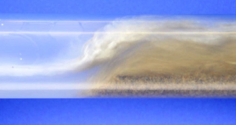
The upper transport boundary for solids in fluid flow is set by the Erosive Limit. This limit sets the maximum fluid velocity for tolerable erosion.
There are several methods for calculating erosion in oil & gas piping, and I will be reviewing only two – API RP 14E and University of Tulsa ECRC Model. (Note: this does not constitute an endorsement of these models – they are used because of the availability of published information).
API RP 14E
American Petroleum Institute RP 14E entitled “Recommended Practice for Design and Installation of Offshore Production Platform Piping Systems” (published in 1991, and reaffirmed 2013), is the default used for calculating erosive limit. The term “default” does not mean it is the best method, just that it has been around for sufficient time that it has permeated our industry.
The formula used from this method calculates the maximum recommended erosional velocity (Ve). It is very simple to use but is very conservative – i.e. leads to overdesigned system. The basic formula is presented as follows: Ve = c/√(ρm)
In this formula Ve is recommended fluid velocity (ft/s), c is empirical constant, and ρm is gas/liquid mixture density (lb/ft³).
The key factor in the equation is “c”, which has the following values in solids-free service;
- 100 for corrosive service (continuous)
- 125 for corrosive service (intermittent)
- 150 for non-corrosive service (continuous)
- 200 for non-corrosive service (intermittent)
Example: sand slurry evacuated by eJECT™ cyclonic jetting transporter (sand in produced water), which has intermittent service using carbon steel pipe. (See reference below for eJECT™ description and further details on this example).
Using values of c=125 and ρm=1070 kg/m³ (66.8 lb/ft³), therefore Ve=15.3 ft/s (4.7 m/s).
This method has no consideration for sand size, concentration, or particle shape.
ECRC Model
The University of Tulsa Erosion/Corrosion Research Center has published a model evaluating API RP 14E and providing an alternative method of calculation. This model seems to be well accepted within the upstream oil & gas industry, but unfortunately details of the model are only available for the ECRC members.
Shell DEP 39.01.10.11-General recommends using U of Tulsa model to assess sand production for increased oil and gas flow. Specifically, “Sand production should be evaluated. Enhanced hydrocarbon production may be possible if sand can be handled and disposed of, but the impact of sand on the flowlines, chokes, separators and pumps needs to be assessed to make a decision on how much sand can be produced.”
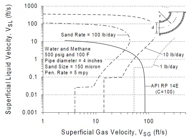
The full model is mechanistic based with empirical parameters gained from the ECRC test program. Some details of the model can be gained from various publications, including SPE 56812. Using Figure 6-8 of this paper (shown below), and using zero superficial gas velocity, the single-phase flow from the preceding example would yield >100 ft/s (>30 m/s) flow rate.
This model will be referred to again in a future article when we look at critical particle size for remediation.
So in evaluating slurry transport, we first calculate the upper transport velocity, which is set by the Erosive Limit. There are other methods (e.g. DNV RP 0501, CFD, proprietary in-house and 3rd party models, etc.) than what was presented here, but I will use API RP 14E in my examples – simply because it is available and easy to use, but knowing full well that it is very conservative. However in FSM design, the erosion limit is not the most important velocity. The lower boundary – termed Saltation Limit – is more important to determine the minimum velocity to carry the solids and prevent pipeline blockage.
References:
- McLaury, B.S., and Shirazi. S.A. 1999. “Generalization of API RP 14E for Erosive Service in Multiphase Production”. Paper 56812 presented at the SPE Annual Technical Conference and Exhibition, Houston, Texas, 3-6 October. https://doi.org/10.2118/56812-MS
- Rawlins, C.H. 2016. “Design of a Cyclonic-Jetting and Slurry-Transport System for Separators”, Oil & Gas Facilities, Vol. 3, No. 1, February, pp. 38-46. https://doi.org/10.2118/166118-PA