The previous article listed the four main components of a liquid desander system. I’d like to address the core two components – vessel and liners – in a bit more detail in this article. The design features listed are what you should evaluate when designing or purchasing a desander unit.
Vessel Design
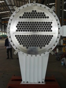
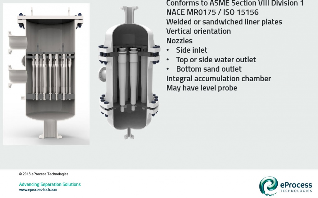
- The graphic below shows two different type liner style vessels. Each vessel meets ASME Sec VIII Div. 1 rating.
- The left vessel has welded mounting plates, while the right vessel has sandwiched mounting plates. Both are fully functional and valid designs. The sandwich design is more expensive but allows access to all internal surfaces of the vessel.
- Inlet nozzle on each is through the side (to middle chamber). The overflow nozzle on the welded plates is through the top chamber side, while the overflow is out the top dished head on the sandwiched plates. Both are functional and valid designs. The overflow side nozzle allows removal of the top flange plate to reach the liners without disconnecting overflow piping.
- The inlet chamber (between the plates) may have a small size nozzle to allow draining of fluids during maintenance.
- The sand outlet on both is directly out the bottom. That is the preferred orientation, especially if a secondary accumulator is used (i.e. straight path fall for the sand).
- The bottom chamber on each is the integral accumulation chamber. This chamber usually has a side nozzle for mounting a level switch.