eProcess Technologies

Multiphase Desander – Pressure Drop and Fluid Throughput (B-FSM087)

Note: The hydraulic pressure drop model for a multiphase desander builds on the methodology presented for a liquid desander as detailed in post B-FSM-060. I recommend strongly to read the previous material first.

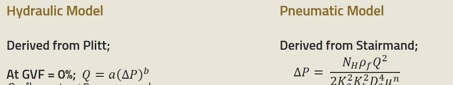
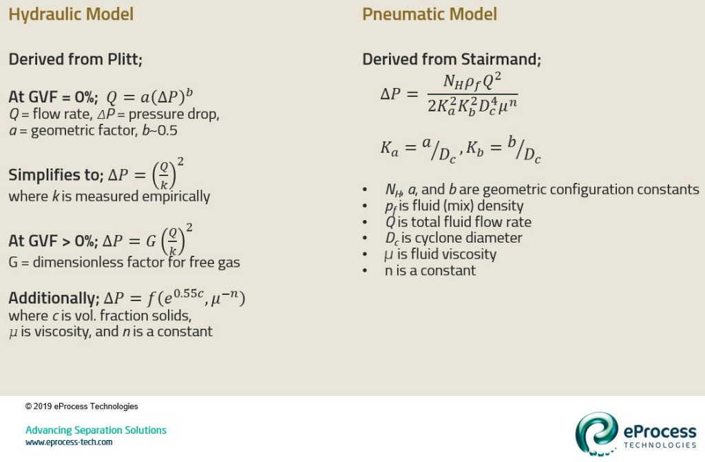
The first step in modeling a multiphase desander is to determine the operating pressure drop. The multiphase fluid throughput relationship is built from the hydraulic and pneumatic cyclone models. These are listed below.

Hydraulic Model

  • Based on Plitt liquid cyclone model (reference below)
  • Use a geometric k-factor based on cyclone geometry
  • Modified for free-gas content using a dimensionless factor (G) based on gas:liquid ratio
  • Both k and G factors are determined in the laboratory for the geometric cyclone model
  • Pressure drop minor factors include fluid viscosity and solids concentration
  • Used for liquid-dominant operating regime

Pneumatic Model

  • Based on Stairmand relationship (referenced in Benitez below)
  • Incorporates specific geometric constants for the cyclone model
  • Uses “heavy” gas – which is fluid mixture density and viscosity
  • Used for gas-dominant operating regime

An example of these models will be presented after the separation size and collection efficiency models are presented in the next article.

References

  1. Benítez, J. 1993. Process Engineering and Design for Air Pollution Control. Upper Saddle River, NJ: PTR Prentice Hall.
  2. Plitt, L.R. 1976. A Mathematical Model of the Hydrocyclone Classifier. CIM Bulletin 69 (776): 114-123.
  3. Rawlins, C.H. 2017. “Separating Solids First – Design and Operation of the Multiphase Desander”, paper 185658-MS presented at the SPE Western Regional Meeting, Bakersfield, CA, 23-27 April.
0 Comments
Inline Feedbacks
View all comments
 
 
white

Copyright © 2024 eProcess Technologies.