Cyclonic jetting is an improved alternative to traditional separator spray jetting. It was developed to improve on some of the shortcomings of spray jetting. A comparison between cyclonic and spray jetting will be covered in a future post.
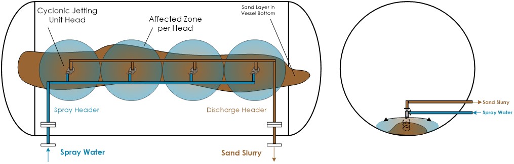
As an introduction, a schematic of a cyclonic jet system (my design) is shown in the header graphic. It contains the following features:
- A jetting water header running the length of the vessel (may be partitioned into sections). This header provides the spray water used to move the settled sand to the cyclonic jetting head suction.
- This header feeds the cyclonic spray for each unit head. Each head imparts a zone of influence in a circular pattern around the head. The spray water fluidizes the settled solids to allow evacuation through the head suction outlet.
- The cyclone jetting system does not use a central sand pan or bottom slurry outlet nozzles. Instead the sand is evacuated through the same cyclonic jetting head.
- Typically the cyclonic spray and the sand evacuation are activated at the same time.
- Control of this type system and the pros/cons will be discussed in future post.
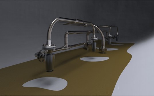
The picture below shows a graphic of the cyclonic jetting system installed in a horizontal vessel. The system shown is the inline type. A square cluster type is available as well.