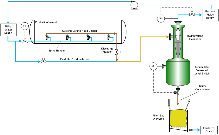
Equipment Layout
- Cyclonic jet clusters (linear or square) in production vessel – one cluster in operation at a time (batch)
- Pre-fill/Post-flush line with spray and slurry headers
- Desander sized for single cluster flow to remove sand and return liquids to process
- Accumulator volume for multiple cluster collection – batch discharge by LS or time
- Filter-bag/bin for final dewatering and transport
Process Operation
- Pre-fill slurry header and desander/accumulator to nominal operating velocity
- Open slurry header and set flow rate (DPC) then spray header (FC), close pre-fill during operation
- Discharge duration based on time or slurry density
- Close slurry discharge
- Post-flush to sweep solids from piping
- Accumulator solids batch discharge into filter bag/bin
- Entire system should be automated
General Design Factors
- Slurry discharge from jetting must be transported to specific target location that does not impede flow from jetting operation
- Includes piping, fitting, instrument, valve, or unit processes
- Slurry dewatering system can be designed to return process liquids back to separator vessel (closed loop)
- Include removal/transport/replacement of solids bin/bag in process operation
- Always pre-fill and post-flush piping that is used to transport slurry
- Automate entire system to ensure robust operation
Next week I will finish the discussion on jetting systems with key items and technical paper references.
References:
- Rawlins, C.H., “Design of a Cyclonic Solids Jetting Device and Slurry Transport System for Production Systems”, paper 166118, presented at the SPE Annual Technical Conference and Exhibition, New Orleans, LA, 30 September – 2 October, 2013. https://doi.org/10.2118/166118-MS