
Where to Remove Sand from Oil & Gas Facilities (B-FSM06)
Commensurate with knowing what problems sand causes – erosion, filling, interference, or increased OIW content – is then knowing where to remove the sand. A primary directive is to solve the right problem. If replacement of choke beans is a hindrance to sustained production, then remove the sand at the wellhead. However, if protecting the disposal reservoir from increasing injection pressure, then sand should be removed from the produced water stream.
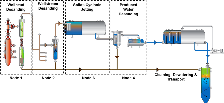
Sand is removed from facility flow in one of four nodes.
Node 1: Wellhead
- Multiphase flow at high pressure
- Sand removed prior to choke using multiphase desander or dual-pot sand filter
- Separation is easy due to low multiphase viscosity and sand easy to handle because of less complication from process chemicals
- Removal of sand here protects choke, manifold piping, production separator, and produced water equipment and disposal
Node 2: Wellstream
- Multiphase flow at medium pressure
- Sand removed on production manifold (before production separator or slug-catcher) using multiphase desander
- Separation is easy due to low multiphase viscosity and sand easy to handle because of less complication from process chemicals
- Can treat combined flow from many wells
- Removal of sand here protects production separator and produced water equipment and disposal
Node 3: Separator (Cyclonic) Jetting
- Static liquid-bath at bottom of production separator
- Sand removed from production separator by cyclonic jetting transporter
- Separation aggravated by sand consolidation (mechanical effect) or binding (chemical effect) – sand should not be allowed to set-up and should be fluidized frequently
- Can treat combined flow from many wells
- Removal of sand here only temporarily alleviates filling of vessel – does not protect produced water stream
Node 4: Produced Water Desanding
- Water flow at low pressure
- Sand removed upstream of oil removal equipment using desanding hydrocyclone
- Relatively easy separation unless complications from process chemicals
- Treats combined produced water flow
- Removal of sand here protects oil removal equipment (e.g. deoiler, flotation cell, nutshell filter, etc.) and produced water reinjection (PWRI) reservoir
While solving the right problem is the primary directive for which node to choose, other factors – such as access to equipment, space & weight constraints, fluid properties, and manpower – are all design points. These factors will be each be discussed in future posts.
The next few posts however will discuss the type and nature of produced solids.
Bibliography:
- Rawlins, C.H., and Wang, I. I., “Design and Installation of a Sand Separation and Handling System for a Gulf of Mexico Oil Production Facility,” SPE Production and Facilities, paper 72999, Vol. 16, No. 3, 2001, pp. 134-140.
- Rawlins, C.H., “Sand Management Methodologies for Sustained Facilities Operations,” paper 164645-MS, North Africa Technical Conference & Exhibition, Cairo, Egypt, 15-17 April 2013.
- Rawlins, C.H., “Design of a Cyclonic Solids Jetting Device and Slurry Transport System for Separators”, SPE Oil and Gas Facilities, February 2016, pp. 38-46.