
FSM: Liquid Desander – Operation Differences between Single and Multi-Cone Vessel Design (B-FSM048)
Continuing with comparison of Single versus Multi-Cone vessel design – we will now look at the operational differences. This explains why these two different designs exists.
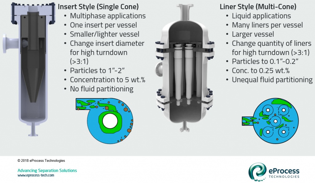
As per previous we will start with schematics of these two types of desander packaging – Single Cone (SC) versus Multi-Cone (MC).
Number of Cyclones per Vessel and Vessel Size
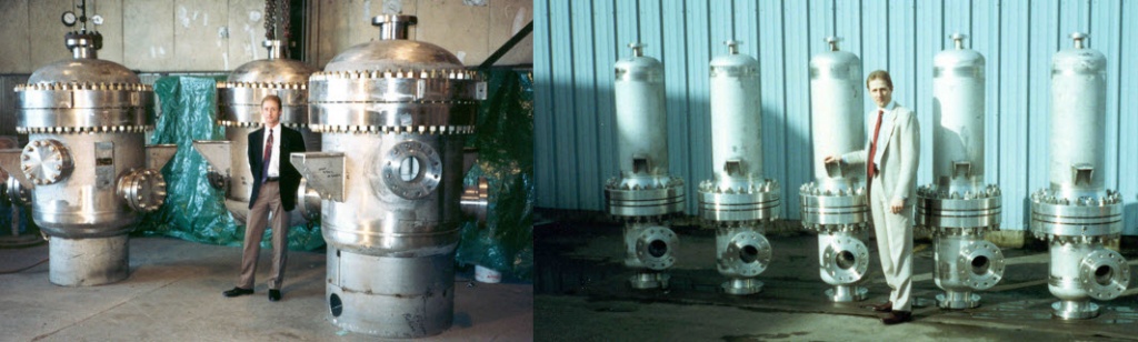
- To reiterate (in case someone didn’t read the previous article) the Single Cone design has one cyclone or “insert” per vessel. The Multi-Cone design has multiple cyclones or “liners” per vessel.
- For a given flow rate, the Single Cone design will result in a smaller diameter (and lighter) vessel compared to the Multi-Cone packing arrangement. This is because with the multi-cone design the distribution space of the inlet chamber is added to the space taken up by the liners. The smaller diameter (hence thinner wall) of the insert style desander is very important at high design pressures. The insert style may have 25-30% the wall thickness compared to a liner style desander at 10,000 psig rating (i.e. wellhead desander).
Cyclone Diameter – Separation Size and Throughput
- The reason many different diameters of desanders exist is separation performance and throughput. Separation size (i.e. size of particle removed from liquid stream) is directly proportional to cyclone diameter. The smaller the cyclone the smaller the particle that can be removed. However, throughput is inversely proportional to cyclone diameter. The smaller the cyclone the less fluid can be treated. For high fluid volumes of fine particles required many small cyclones operating in parallel. We will cover how to calculate separation size and throughput in a future article.
Turndown
- Each cyclone has ~3:1 turndown for liquid flow. For higher turndown with the insert style, the entire insert must be changed (smaller or larger as vessel allows). With the multi-cone typically the quantity of active liners is changed – i.e. liners replaced with blanks and vice versa to accommodate turndown or turnup. In both cases the vessel should be sized for the highest flow rate and insert size or number of liners changes as appropriate for turndown.
Particle Size
- The largest particle size a cyclone can treat is 1/3 the diameter of the smallest orifice. For example, a 10-inch diameter cyclone with 2.5-inch diameter inlet, 3-inch diameter vortex finder, and 1.5-inch diameter apex can treat a maximum size particle of 0.5-inch (e.g. 1/3 diameter of the apex). Since the insert in a single-cone design is always larger than the liner in a multi-cone design, the Insert Style desander can treat fluid with larger particle size. In general the insert style can treat particles 2.5-5.0 cm diameter, while the liner style can treat particles 2.5-5.0 mm diameter.
Particle Concentration
- Too many particles (i.e. high solids concentration) can over-crowd a hydrocyclone, which both reduces separation performance and wear life. This is even more important with a desander which has a batch discharge on the underflow (note: particle transfer between cyclone and accumulator and desander will be covered in detail in future post and new SPE paper). How many particles is too many, or at what point will the desander choke? The effective operating concentration is directly proportional to cyclone diameter. Larger cyclones can handle higher concentration of solids. The range varies with solids and fluid properties, but insert style desanders can treat up to 5 wt.% solids, while liner-style desanders are <0.5 wt.% solids.
Fluid Partitioning (Liquid versus Multiphase Flow)
- All fluids entering a insert-style desander are treated together by the single cone. However in a multi-cone design if multiphase fluids are present, then unequal fluid partitioning may take place. Some liners will have predominantly gas and some will have predominantly liquid. This leads to short circuiting, liquid packing, and overall degraded performance. If multiphase flow exists, then always use an insert style desander to prevent fluid partitioning.
When to Use What
- For produced water treatment – which has small particle size (all large particles are captured in the upstream production separator), low particle concentration, liquid only flow, and small particle capture requirements (i.e. to protect downstream liquid-liquid cyclones) then use a multi-cone desander vessel. For jetting slurry treatment or multiphase (wellhead) desanding use a single-cone design. Jetting slurry has too high concentration for the multi-cone design. Multiphase flow (especially wellhead desanding) has large particle and high particle concentration from raw well flow, gas-liquid mixed flow (i.e. potential for fluid partitioning), and very high-pressure rating (i.e. you want a smaller diameter vessel) – then use the insert-style desander.
The next article will discuss fluid and particle flow profile within hydrocyclones and desanders.
References
- Rawlins, C.H. and Wang, I.I. 2001. Design and Installation of a Sand-Separation and Handling System for a Gulf of Mexico Oil Production Facility. SPE Production & Facilities, August, pp. 134-140.
- Rawlins, C.H., “Separating Solids First – Design and Operation of the Multiphase Desander”, paper 185658-MS presented at the SPE Western Regional Meeting, Bakersfield, CA, 23-27 April, 2017.
- Rawlins, C.H., “Particle Transfer Between the Cyclone and Accumulator Sections of a Desander”, paper SPE-191147-PA (accepted). SPE Production & Facilities, 2018.
- Svarovsky, L., “Hydrocyclones”, Technomics Publishing Co. Inc., Lancaster, PA, 1984.