The following information is to accompany the previous graphic.
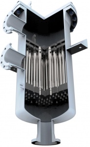
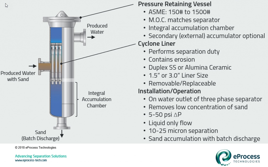
- The pressure retaining vessel is designed to hold the cyclone liners. It is made of an appropriate material for corrosion control and appropriate design rating to match the system requirements. Most liquid desanders are on produced water streams and designed to ASME Sec VIII Div 1 code at 150#-600# rating.
- The cyclone liner is sized to perform the separation duty. It also contains all erosion. It is a replaceable (consumable) component. To handle higher flow rates requires more liners (and a larger diameter vessel). The liners are made of erosion resistant material – either ceramic (i.e. alumina) or wear resistant metal (i.e. Stellite®).
- Most liners are sized at 1”, 1.5”, 2”, or 3” diameter. These size liners will separate 10-25 micron sand from water. Note: the practical limit for sand removal from produced water with cyclonic technology is 10 microns. Smaller separation size is possible (i.e. 5-7 micron separation with 0.5” desander – but the number of units and packing becomes impractical for general produced water treatment).
- For produced water treatment the desander comes first. It is located directly off the water leg of a three-phase separator and before any oil removal equipment (i.e. deoiler or flotation cell).
- The produced water (liquid) desander is designed to remove low concentrations (<250 ppmw) of small-medium size sand (<150 micron) on a continuous basis. In this application it treats liquid only flow.
- The normal operating pressure drop range is 5-50 psi. Below 5 psi the desander has insufficient fluid velocity and the cyclone vortex collapses. Operating >50 psi is great for separation, but erosional life of the cyclone liner drops off sharply.
- As mentioned previously, separation is continuous but sand removal (from accumulator) is a batch (periodic) discharge operation.
The next article will discuss particle travel within the desander and accumulator.
References
- Rawlins, C.H., “Particle Transfer Between the Cyclone and Accumulator Sections of a Desander”, paper SPE-191147-PA (accepted). SPE Production & Facilities, 2018.