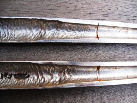
The header graphic shows two 38 mm desander liners that were used until erosive failure. What I find interesting is that the liners didn’t fail at the bottom of the cone – where the rotational velocity and solids concentration is the highest – but in the upper cone and cylinder. In fact the lower cone shows very little wear. I was puzzled by this result but research into the operation of this desander, and a demonstration in the laboratory, showed me that the failure was due to solids overload. The apex was choked – due to high inlet solids concentration – and the rotating mass of solids in the upper portion of the liner wore away at the material. This liner was installed into a vessel designed to treat produced water with <500 ppm solids. However, the operator also used this exact same desander to try and remove solids from their separator jetting slurry – which had up to 40 wt.% sand. The separation performance was poor, and the liners failed. A liner style desander (i.e. multiple small desander liners in a vessel) should never be used to treat jetting slurry. That is the duty of a slurry desander – which uses a 200 mm or 250 mm desander insert.
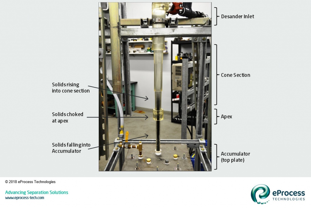
The photo below is a still shot from a video showing the operation of a 50 mm clear urethane hydrocyclone configured as a desander (i.e. flooded-core with accumulator). This desander is treating 12/20 mesh coal in water (coal used to visualize the particle travel). The desander inlet is at the top right of the photo, with the overflow out the top middle. The particles travel in a vortex pattern down the length of the cylinder and cone – and are first visible just above the apex. In this operation I have overloaded the desander with a high concentration of coal particles. The particles are choked at the apex. Particles are still falling through the apex into the accumulator, however they are reporting to the apex from the inlet faster than they can fall. Thus, the overload of particles is starting to rise into the cone section. Eventually the backed-up material will fill the cone and report to the overflow. The apex and accumulator are still working properly – albeit at the maximum solids they can handle. This action is best seen from viewing the video here. (Note: at the end of the video I introduce an apex flux balance line – that will be detailed in a subsequent post).