Facilities Sand Management: Calculations – Slurry Density and Volume Fraction (B-FSM023)

Note: This article is a continuation of B-FSM-22. See the previous article for some definitions and terms.
Slurry Density
Concentration (terms defined previously) can be used to calculate slurry density. The slurry density is the weight per unit volume of the solid-liquid mixture. In most production cases, with low concentration solids such as 100 ppmw or 100 mg/l, the slurry density will be nearly identical to the liquid density. In high production of solids, or transport of settled solids – such as jetting discharge or accumulator purging – the slurry density will vary widely from that of the liquid.
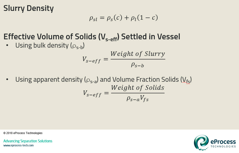
The definition is given in the figure below, and at the end of this article I will provide some worked out examples. Slurry density (ρsl) is calculated from the solid (ρs) and liquid density (ρl), and the volume fraction solids (c).

Effective Volume of Solids Settled in a Vessel
Solids settle in low-velocity zones within the production system – sometimes by design and sometimes to the detriment of equipment operation. Produced solids are particulate by nature and do not pack fully in a volume. As per article B-FSM-014 the volume fraction of solids determines the conversion from solids concentration to settled volume.
The figure above shows how to calculate the effective volume of settled solids (i.e. in bottom of a production separator for example) from either bulk density (ρs-b) or solids apparent density (ps-a) and volume fraction (Vfs). The latter equation will be used in the example that follows.
Example Calculations
This example comes from a system I’m currently designing.
Input Data:
- Liquid Flow: 4000 BPD at 1076 kg/m³ density
- Solids Concentration: 470-2000 pptb (pounds per thousand barrels)
- Solids Properties: 2650 kg/m³ density and 0.63 volume fraction (when settled)
Calculation Steps – Slurry Density:
Q: What is the effect of solids on the fluid density?
- Weight of solids per 1000 BBLS liquid: (low) 470 lbs = 214 kg to (high) 908 kg
- Volume of solids per 1000 BBLS liquid: 214/2650 = 0.081 m³ to 908/2650 = 0.343 m³
- Volume of 1000 BBLS liquid = 158.97 m³
- Volume fraction solids low: c = (0.081/(0.081+158.97)) = 5.093×10⁻⁴ (or 509 ppmv)
- Volume fraction solids high: c = (0.343/(0.343+158.97)) = 2.15×10⁻³ (or 2153 ppmv)
- Slurry Density (high case): ρsl = (2650)(2.15×10⁻³)+(1076)(1-2.15×10⁻³) = 1079 kg/m³
A: At the highest production rate (2000 pptb) the slurry density is marginally different from the liquid density.
Calculation Steps – Settled Volume of Solids:
Q: What is the volume of solids from one-day production, assuming all solids (100% capture at worst case) settle into the production separator?
- Total liquid volume: 4000 BBLS = 635.88 m³
- Volume fraction of solids (high): 2.15×10⁻³
- True volume of solids in liquid stream: (635.88)(2.15×10⁻³) = 1.369 m³
- Effective volume of settled solids: 1.369/0.63 = 2.173 m³
A: Each day produces ~ 2 cubic meters of solids
Calculation Steps – Transport of Settled Solids:
Q: What is the slurry density of the solids jetted from the separator?
- The process of solids jetting and design of slurry piping will be fully covered in a future article. Further details can be found in the reference listed below.
- For now we’ll calculate the average jetting slurry density (jetting slurry starts at 60-70 weight percent solids and drops to <5 weight percent depending on jetting time). For the basis of this calculation we’ll assume the average density is 20 weight percent solids.
- Solids weight fraction: w = 20%/100 = 0.20
- Solids volume fraction (see previous article for conversion):
- c = (0.20/2650)/((0.20/2650)+(1.0-0.20)/(1076)) = 0.092
- Slurry density: ρsl = (2650)(0.092)+(1076)(1-0.092) = 1201 kg/m³
A: The slurry density is ~1200 kg/m³, which takes more energy to transport through piping than liquid alone.
The next article will cover calculations for particle settling rate.
References:
- Rawlins, C.H. 2016. “Design of a Cyclonic-Jetting and Slurry-Transport System for Separators”, Oil & Gas Facilities, Vol. 3, No. 1, February, pp. 38-46. https://doi.org/10.2118/166118-PA
