I’m a firm believer that solids should be removed from the flowline upstream of the production or test separator. See paper “Separating Solids First – Design and Operation of the Multiphase Desander” in reference below.
However, if sand does make to the production separator, it will settle in the low velocity zones – which happen to be the water section of your separator. You can remove the sand using cyclonic jetting (see Oil & Gas Facilities reference below).
But how do you calculate the quantity of sand and of what size that settles in your separator?
Industry Guidelines
The first thing I did was check industry standards and references on methods to calculate sand settling in separators. These did not provide what I was looking for.
- API 421 Design and Operation of Oil-Water Separators
- Amount of settleable solids determined by Standard Method 2540F or EPA Method 160.5 (same procedure) – uses 1 liter of sample in Imhoff cone for 1 hour – records amount directly
- NORSOK P-100
- Provision for jetting/pan system – no calculations
- Shell DEP 31.22.05.12-Gen.
- Provision for liquid spray/drain, reduce inlet velocity, add erosion allowance to inlet device – no calculations
- Surface Production Operations (Vol. 1) by Arnold and Stewart
- Provision for jets/pans – no calculations
- GPSA Engineering Data Book
In discussions with engineers at several operators (ExxonMobil, BP, Chevron, Statoil, etc.) the consensus was to base solids settling on Stokes approximation.
Stokes / Mass-Balance Method
Using this method (Stokes settling has been discussed in article B-FSM-24) I put together a simple procedure for estimating cut-size and quantity of settled solids. This uses a simple mechanistic, mass-balance approach detailed in the following steps.
- Calculate residence time of liquid (water) in vessel (weir height and inlet to weir distance)
- Calculate fall (capture) velocity as vertical distance divided by residence time
- Use Stokes Law to calculate size of particle matching capture velocity
- Particles with diameter greater than capture size are collected within the separator – smaller particles pass through with produced water
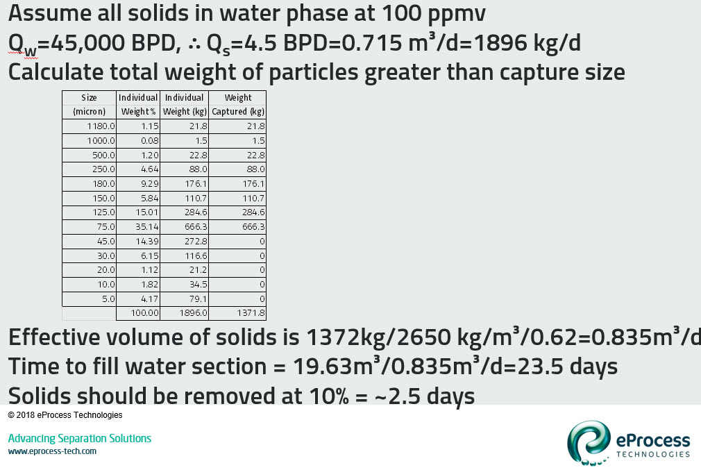
- Sum of all particles greater than capture size gives total amount of solids settled in separator
Example – Part 1: Calculate Capture Size
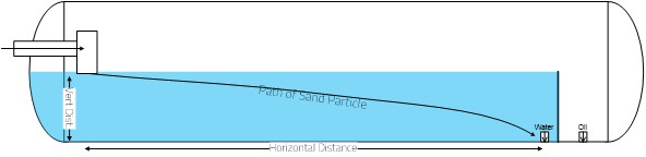
The following example is detailed in the two graphics as follows.
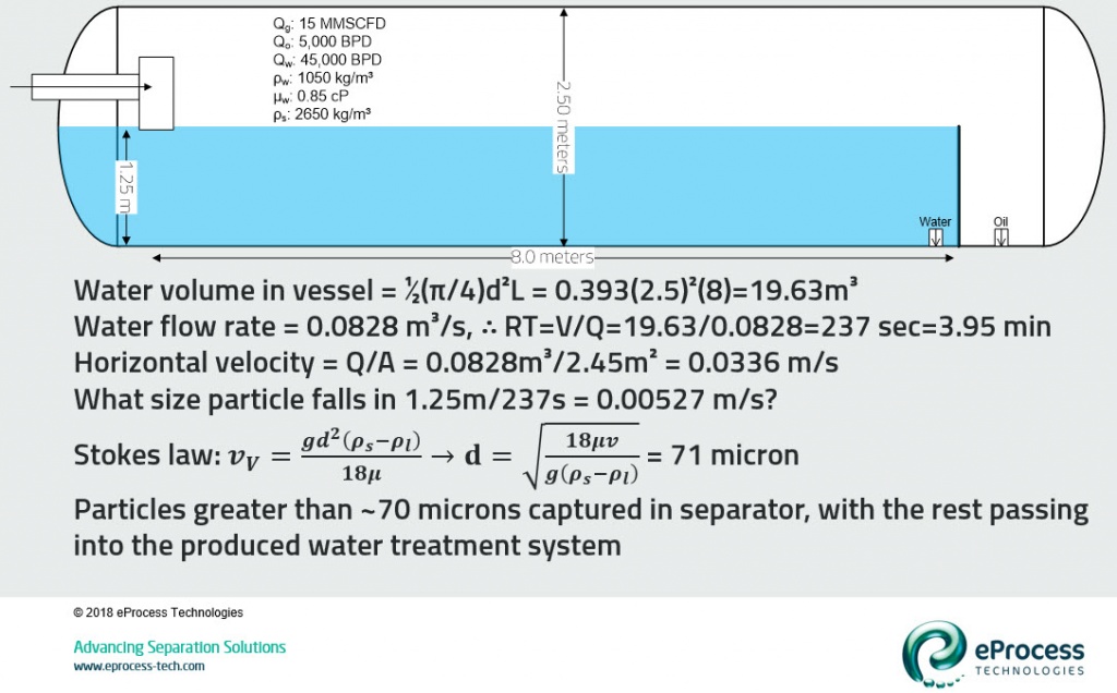
- Separator: 2.5 meters (8 feet) diameter, inlet-water length of 8 meters (~28 feet), water depth of 50% (shown on graphic below)
- Process Conditions: 50,000 BLPD at 90% water cut, produced water at 1050 kg/m³ density and 0.85 cP viscosity, and sand at 2650 kg/m³ density
- I’ve used a simple Stokes calculation (I didn’t check validity with Re, but this is good for a first pass)
- First calculate water residence time (using water volume in vessel and water flow rate), which is 3.95 minutes (237 seconds)
- Second determine what size particle falls the full depth (1.25 m) of water in 237 seconds = 71 microns. So, particles greater than ~70 microns are captured in the production separator and the rest passes to the produced water stream
- Yes, this is a very simplistic calculation that ignores turbulence, short-circuiting, internals, etc.