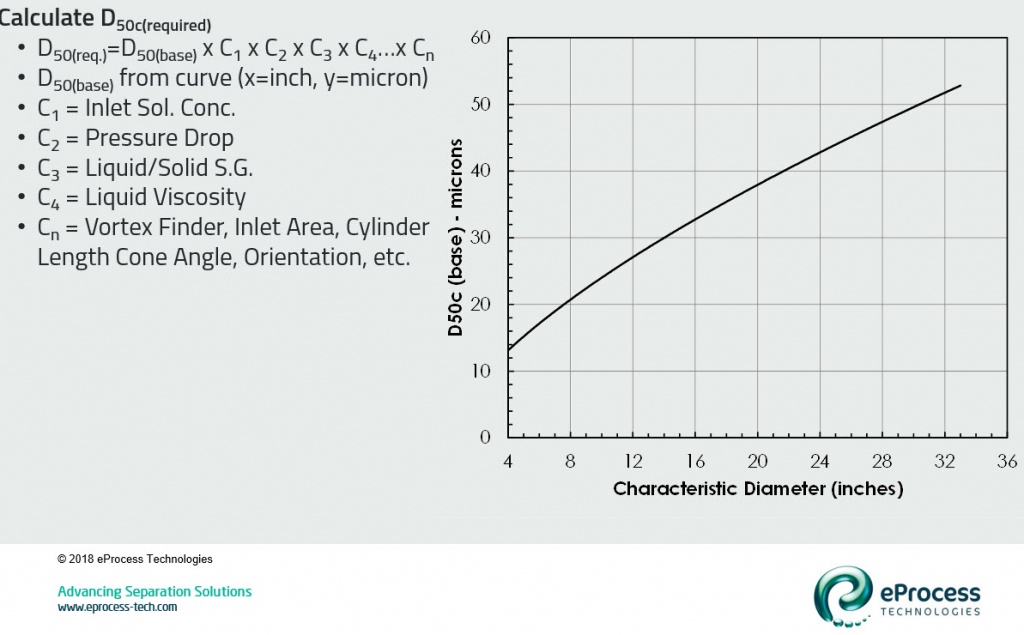
The D50base is based solely on desander characteristic diameter (Dc). The characteristic diameter is the internal diameter of the cylindrical section. For example, a 3” liner style desander has an I.D. of 3” (76 mm), while a 10” insert style desander has an I.D. of 10” (254 mm). The D50base is read directly from the chart shown in the above graphic (plots desander diameter on abscissa and D50base on ordinate). The 10” insert style desander has a D50base of 22 microns.
This 22 micron base (for example) would then be multiplied by correction factors that may increase or decrease the cut size. Four correction factors will be detailed in subsequent posts. These include;
- C1: correction for solids concentration in the inlet fluid
- C2: correction for pressure drop
- C3: correction for solid:fluid density ratio
- C4: correction for fluid viscosity
Many other corrections are also applied – including diameter of vortex finder, diameter of inlet slot, length of cone section, included angle of cone section, orientation of desander, particle shape, etc. These are proprietary relationships that will not be published. However the corrections above will be sufficient for first-order analysis.
The required cut point (D50req.) – which is our goal – is the product of the D50base and these correction factors.
The next article discusses corrections for solids concentration (C1) and pressure drop (C2).
References
- Plitt, L.R., “A mathematical model of the hydrocyclone classifier”, CIM Bulletin, December, 1976, pp. 115-123.
- Rawlins, C.H., and Wang, I. I., “Design and Installation of a Sand Separation and Handling System for a Gulf of Mexico Oil Production Facility,” SPE Production and Facilities, paper 72999, Vol. 16, No. 3, 2001, pp. 134-140.
- Svarovsky, L., “Hydrocyclones”, Technomics Publishing Co. Inc., Lancaster, PA, 1984.