eProcess Technologies

Liquid Desander – Flow Sheet Design (B-FSM076)

Incorporating a desander into produced water treatment prior to a deoiler

There is a myriad of flow sheet design options for liquid desanders. These depend on location, type of operation, materials, pressure rating, safety requirements, level of operations, etc. I will keep this very simple and you as an engineer need to adapt as appropriate to your facility. If you have any questions email me. While we standardize the liners and vessel packing, the many options available prevent standardizing the skid or system.

Simple PID

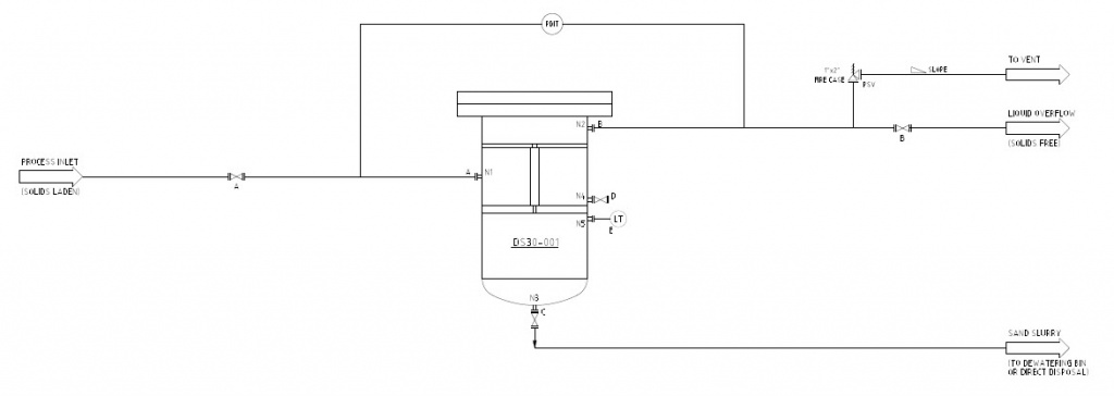
The graphic blow shows an example or standard PID to start with. This drawing lists a liner desander vessel with basic input and output lines. Process inlet enters the side of the vessel through N1. Liquid overflow is out the top-side (N2), while underflow solids are directly out the bottom (N3). A level switch may be installed (N5) in the underflow chamber and a drain point (N4) may be installed on the inlet chamber. Pressure differential measurement is made from inlet-overflow to monitor operation. Many operations require a fire-save PSV for the vessel which most commonly is installed on the overflow line. Pretty simple system design.

Offshore Example

The graphic below shows are more comprehensive system. This is more of a flow-schematic than a PID. This system is detailed in the reference listed (i.e. SPE 72999). Each desander (liner style, welded plates, 150# rating) has PIT on inlet and overflow lines to calculate pressure drop. A level switch activates the underflow dump valve. Each desander is installed with a bypass line to allow maintenance on the vessel without interrupting production.

Integration with Deoiler Hydrocyclone

Produced water desanders are most commonly used prior to a deoiler hydrocyclone. The desanders serves to remove sand and prevent erosion on the deoiler liners. The desander part of the PID below is very simple. Again, we just need to monitor desander pressure drop and purge the collected sand periodically. From a process point of view the desander is simply a pressure drop in the liner before the deoiler.

The next article will provide a summary, key items, and technical references for liquid desanders.

References:

  1. Ditria, J.C., Hoyack, M.E. 1994. “The Separation of Solids and Liquids With Hydrocyclone-Based Technology for Water Treatment and Crude Processing”, paper 28815, SPE Asia Pacific Oil & Gas Conference, Melbourne, Australia, 7-10 November.
  2. Rawlins, C.H., and Wang, I. I. 2001. “Design and Installation of a Sand Separation and Handling System for a Gulf of Mexico Oil Production Facility,” SPE Production and Facilities, paper 72999, Vol. 16, No. 3, pp. 134-140.

Comments are closed.


white

Copyright © 2024 eProcess Technologies.