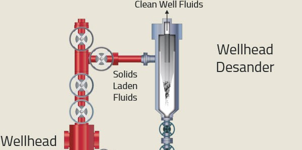
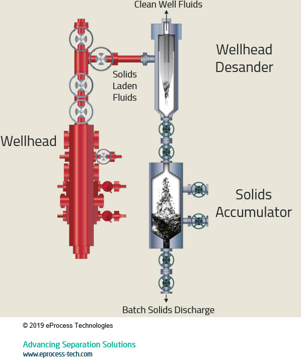
The layout, configuration, and general flow scheme of a multiphase desander – installed as a wellhead unit – is shown in the graphic below.
Pressure Retaining Vessel
- The pressure retaining housing of the multiphase desander contains the process pressure and fluids. It is design to match the appropriate design conditions and materials to the wellhead (upstream of choke) or manifold (downstream of choke)
- ASME designs are from 150# to 1500# rating
- API-6A designs are 5/10/15 K rating. The API unit (wellhead) is designed for full shut-in pressure and does not require a PSV
Cyclonic Insert
- The cyclonic insert performs separation duty, while containing all erosion
- The insert is replaceable and interchangeable
- Inserts are available in sizes 4”, 6”, 8”, 10”, 16”, and 20”
- Common materials of construction are 410 SS, duplex SS, or Silicon Carbide
Installation/Operation
- As mentioned in previous article, the multiphase desander can be installed upstream of the choke (wellhead unit) and downstream of the choke (wellstream unit)
- The multiphase desander can be installed as a service tool (portable, skid-mounted unit) or production unit (permanent installation)
- General operating range is 5-75 psi pressure drop
- The multiphase desander can operate from 0-100% GVF (all liquid or all gas)
- Separation size ranges from 10-25 micron D98
- With the accumulator unit, the multiphase desander provides continuous separation with on-line batch sand discharge – the desander is not taken off-line to remove the separated sand