eProcess Technologies

Separator Jetting – Cyclonic Jetting Unit Vessel Installation (B-FSM-124)

The orientation and diameter of the vessel to be evacuated of sand determines the method of installation for cyclonic jetting technology.

Horizontal Vessel (<2.0 m diameter)

  • Install per graphic below
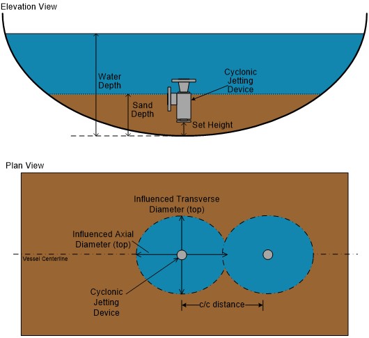
  • A single row of cyclonic jetting unit (in-line cluster) along centerline of vessel
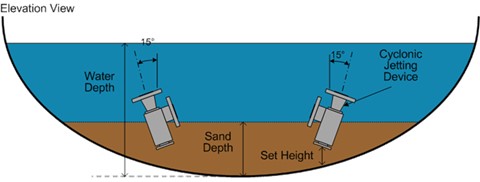
  • Each unit is vertically oriented
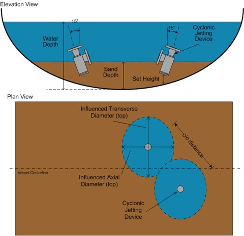
  • Sand removed in ellipse shape – axially oriented with vessel
  • Space each cyclonic jetting head center-center with minimal overlap between major axes of ellipse

Horizontal Vessel (>2.0 m diameter)

  • Install per graphic below
  • A double row of cyclonic jetting unit (square cluster) straddling centerline of vessel
  • The jetting heads are oriented 15° from vertical
  • Sand removed in ellipse shape – transverse oriented with vessel
  • Space each cyclonic jetting head center-center with minimal overlap between major/minor axes of ellipse

Vertical Vessel

  • Use a single unit head for vessels <1.5 m diameter
  • Use multiple unit heads for vessels >1.5 m diameter

Atmospheric Tanks

  • Requires and eductor on slurry discharge for pressure differential ratio (i.e. to evacuate the collected sand)
  • Slurry line must sized for eductor motive flow plus slurry flow

A video of the operation of this technology in a horizontal vessel can be found on our company website here.

Next week I will discuss the installation of the cyclonic jetting system design parameters.

References:

  1. Rawlins, C.H., “Design of a Cyclonic Solids Jetting Device and Slurry Transport System for Production Systems”, paper 166118, presented at the SPE Annual Technical Conference and Exhibition, New Orleans, LA, 30 September – 2 October, 2013. https://doi.org/10.2118/166118-MS
0 Comments
Inline Feedbacks
View all comments
 
 
white

Copyright © 2024 eProcess Technologies.