eProcess Technologies

Separator Jetting – Sand Management Options (B-FSM-112)

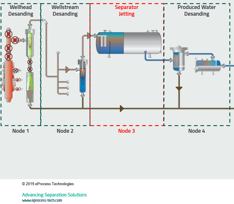
A separator jetting system is used to remove solids that collect or accumulate in gravity separation equipment. These could be slug catchers, free water knock outs, 2/3 phase vessels, dehydrators, CPIs, or any low velocity gravity-based piece of equipment. This occurs in Step 1 of the Solids Handling Methodology flowchart.

The Five-Steps of Sand Management

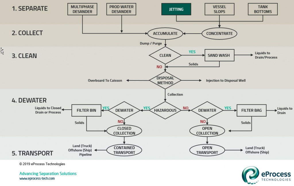
The core of solids handling for the upstream oil & gas industry – whether onshore or offshore – is to follow the Five-Steps of Sand Management. Most approaches for sand management focus on finding a piece of equipment to separate the sand – and assume the work is done. That is only Step 1. It is critical to follow all the steps.

The separator jetting system is used in Step 1 – separation of solids from the flow stream.

  1. Separate: Partition the solid particles from the liquid, gas, or multiphase stream
  • Multiphase desander, filters, or jetting from three-phase separator
  1. Collect: Gather partitioned solids into one central location and remove from process pressure
  • Desander accumulator vessel or vessel drains
  1. Clean: Removal of adsorbed hydrocarbon contaminants
  • Recycle sand-wash systems
  1. Dewater: Removal of free water to minimize disposal volume
  • Hanging mesh bags or screen lined bins
  • Reduce the disposal volume by 90% and produce sand “cake” of <10 wt.% water
  1. Transport: Bring solids to disposal location
  • Dependent upon the facilities location (onshore/offshore) and disposal requirements
  • Options: Overboard discharge, landfill, ship-to-shore, slurry injection, etc.

Where to Remove Sand from Oil & Gas Facilities

Commensurate with knowing what problems sand causes – erosion, filling, interference, or increased OIW content – is then knowing where to remove the sand. A primary directive is to solve the right problem. If replacement of choke beans is a hindrance to sustained production, then remove the sand at the wellhead. However, if protecting the disposal reservoir from increasing injection pressure, then sand should be removed from the produced water stream.

Sand is removed from facility flow in one of four nodes as shown in the header graphic. The separator jetting system is used in Node 3 – within the production separator vessel.

Node 3: Separator

  • Liquid flow at medium to low pressure
  • Accumulator sand removed in batch mode from vessel
  • Separation from flow stream is dependent on vessel residence time, fluid turbulence, and solid-fluid properties. The vessel does the separation duty while the jetting is used to remove the collected sand.
  • Removal of sand here protects produced water treating equipment (e.g., deoilers, flotation cells, CPI, etc.) and final disposal system

References:

  1. Rawlins, C.H., “Design of a Cyclonic Solids Jetting Device and Slurry Transport System for Production Systems”, paper 166118, presented at the SPE Annual Technical Conference and Exhibition, New Orleans, LA, 30 September – 2 October, 2013. https://doi.org/10.2118/166118-MS

Next week I will cover settling of solids in low velocity zones.

0 Comments
Inline Feedbacks
View all comments
 
 
white

Copyright © 2024 eProcess Technologies.