There is no standard design available for traditional spray jetting system used in production separators. In checking several key design resources listed below – several mention adding a jetting and pan system – but do not give design details.
API 421 Design and Operation of Oil-Water Separators
- Amount of settleable solids determined by Standard Method 2540F or EPA Method 160.5 (same procedure) – no calculations
NORSOK P-100
- Provision for jetting/pan system – no calculations
Shell DEP 31.22.05.12-Gen.
- Provision for liquid spray/drain, reduce inlet velocity, add erosion allowance to inlet device – no calculations
Surface Production Operations (Vol. 1) by Arnold and Stewart
- Provision for jets/pans – no calculations
GPSA Engineering Data Book
I will provide a detailed calculation method for traditional jetting design in a future post – but will use the current article to provide information on the general layout and operation.
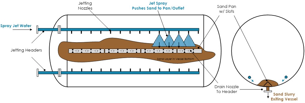
A schematic of a traditional spray jet system (my design) is shown in the header graphic. It contains the following features:
- A spray water header running the length of the vessel (may be partitioned into sections). This header provides the spray jetting water used to move the settled sand to the outlet.
- The spray water header has a number of nozzles located along the length. These are designed to impart a spray jet along the curve of the vessel (shown on right) and pointed towards the base of the settled sand to push the particles to the outlet.
- A central sand pan (inverted trough) running along the centerline of the vessel. This pan covers the outlet nozzles and is supposed to form a channel for directing the jetted sand. The pan has slots at regular intervals into which the sand is directed.
- Outlet nozzles spaced along the centerline of the vessel (under the sand pan) to create a low pressure area for sand removal.
- Typically the spray jets and the sand removal are activated at the same time.
- Control of this type system and the pros/cons will be discussed in future post.
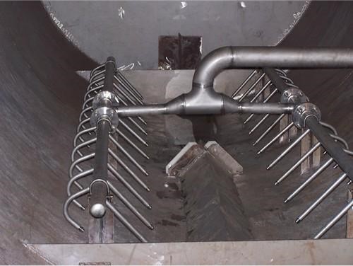
The picture below (from link here) shows a photograph of this type system installed in a horizontal vessel. There is a central spray water supply split into two parallel headers running the length of the vessel. Two levels of spray nozzles on each header each push the sand towards the central sand pan.