Wellhead Screen-Filter – General Design and Operation (B-FSM-102)

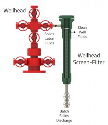
The general design of the wellhead screen-filter consists of a pressure retaining vessel and a cylindrical screen insert.
Pressure Retaining Vessel
- Designed to contain full operating pressure
- Built to API-6A wellhead specifications at 5K, 10K, or 15K rating
- Will contain full shut-in pressure and no PSV is required
Cylindrical Screen Insert
- Held inside the pressure vessel and performs the sand separation duty
- Typically made from 316 stainless steel
- An example design is 15 cm (6”) diameter x 3 meter length = 50 liters sand hold-up volume
- Common separation sizes are 100-400 micron aperture widths at 50 micron intervals
- It is a wedge-wire type with inside-to-out flow (detailed in next post)
Installation/Operation
- The wellhead screen-filter is installed upstream of the choke as a service tool and used to remove coarse solids from flowback
- Operating pressure drops range from 10 psi (clean) to more than 200 psi (dirty)
- This unit can operate fully from 0-100% gas void fraction
- Installation requires 2 x 100% units – with one in operation and one on standby
- Sand is removed by batch discharge from the standby unit
Comparison to Multiphase Desander (same as previous post)
- The Wellhead Screen-Filter and Wellhead Desander are both used as a service tool during well flow-back and clean-up operations
- The WSF is not used in permanent production operations. The multiphase desander in Wellhead or Wellstream version, are commonly installed as a permanent part of facilities to deal with long-term sand production.
- Both devices work in multiphase or liquid-only flow.
- The WSF has infinite turndown as the separation mechanism is not pressure drop dependent. The multiphase desander has a finite (~5:1 turndown) based on the flow-pressure relationship.
- The WSF separate solids effectively down to 100-150 microns, while the multiphase desander can separate down to 15-20 microns.
- The WSF has a 50-60 liter solids hold-up volume before backflush, while the multiphase desander has 150-300 liter solids accumulation volume.
- The WSF requires 2 x 100% layout to allow flushing of one unit while the other is in operation. The multiphase desander stays online at all times during operation, even during solids flushing.
- For the multiphase desander fluid viscosity has a directly proportional relationship with separation size, while the WSF maintains separation performance at all fluid viscosities. However, both units show increase pressure drop with increasing viscosity.
References:
- Rawlins, C.H., “Separating Solids First – Design and Operation of the Multiphase Desander”, paper 185658-MS presented at the SPE Western Regional Meeting, Bakersfield, CA, 23-27 April, 2017. https://doi.org/10.2118/185658-MS
Next week I will cover fluid flow patterns and particle travel of the WSF.
