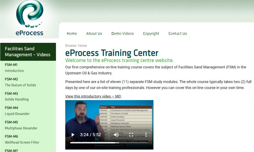
The main training course requires a fee, while the four demo videos are free.
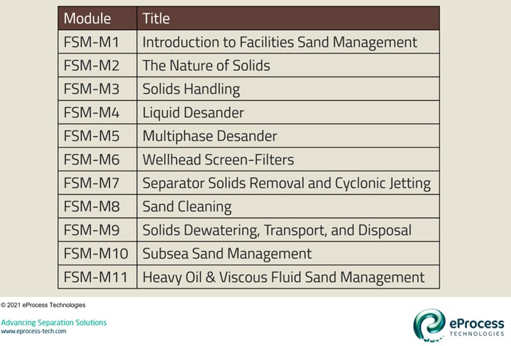
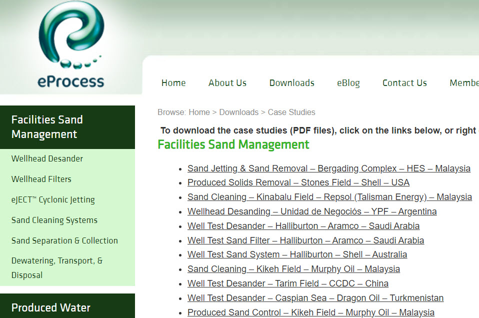
The site focuses on Facilities Sand Management (FSM), which is a specialized subject area previously unavailable to the engineering professional in the oil & gas industry.
This is not a marketing or selling course. Our biggest challenge as a company is the lack of proper information, solid engineering foundations, and consistent and logical work-flow approach to the subject material – in the marketplace.
Our objective is that on completion of the course, the individual will have a solid foundation of knowledge to address and make informed decisions in a qualified manner. They will be able to converse with anyone, including engineering designers, equipment suppliers, and manufacturers regarding design and deployment of a proper Facilities Sand Management solution for their facilities.
I hope you find the information presented useful for your daily activities.
Regards,
Hank Rawlins, PhD, P.E.
Managing Director/CTO
eProcess Technologies
hrawlins@eprocess-tech.com